Resonance has several definitions. From a physical perspective it is a simultaneous oscillation caused by waves tuned to the same period impinging on a body or the ability of a body to oscillate to the same frequency as the source.
Another definition again states that resonance is the tendency of a system to oscillate at a greater amplitude, at some frequencies more than others. These frequencies are known as resonant frequencies. At resonant frequencies, even small periodic forces can cause large amplitudes of oscillation because the system stores the energy of the oscillation.
First, let’s explain what oscillation is. If not affected by external forces, any rigid body remains stationary in space. By adding external energy, the body gains kinetic energy in space, which gives it the moment of momentum. If a body were placed in a vacuum without the influence of gravity, then that body could move practically to the end of the universe (both spatially and temporally). Since we do not encounter many such bodies in our ordinary life, we will deal with conditions close to us. We will consider a body that interacts with its environment. In this case, we can say that if we apply a short pulse of energy to a body at rest, this body will deflect from its stable position, which we call the zero point. Due to gravity, damping, and other physical actions, the body attempts to return back to its original position where it was energetically balanced at zero.
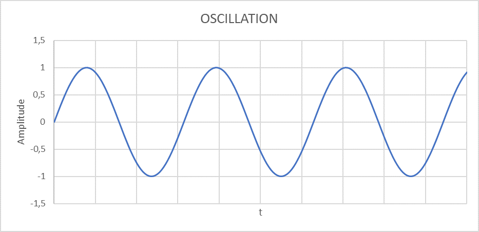
Fig. 1 – Sinusoidal oscillation
Three basic quantities define the frequency and amplitude of oscillation of anybody or system of bodies. Mass, elasticity/rigidity, and damping coefficient. The mass and elasticity are determined by the shape and material of the body and remain constant under standard conditions. The damping coefficient also depends on the interaction of the body with its environment and can vary over time. This variation is reflected in the time required to damp the oscillation of the system.
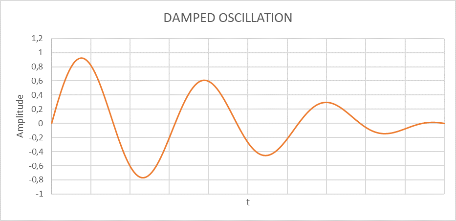
Fig. 2 – Time profile of damped oscillation
What happens if we add a fourth member to the system in the form of an oscillation generator (resonator)?
As mentioned at the beginning of the article, the system stores the energy of oscillation. Therefore, if the frequency of the system and the resonator are in frequency and phase harmony, the resonance of the system will occur and this will be reflected in an increase of the amplitude of the oscillation while maintaining the frequency. This phenomenon is particularly undesirable and dangerous because in some cases it can lead to total destruction of the system. Perhaps the most known case of destruction due to resonance is the collapse of the Tacoma Bridge in November 1940.
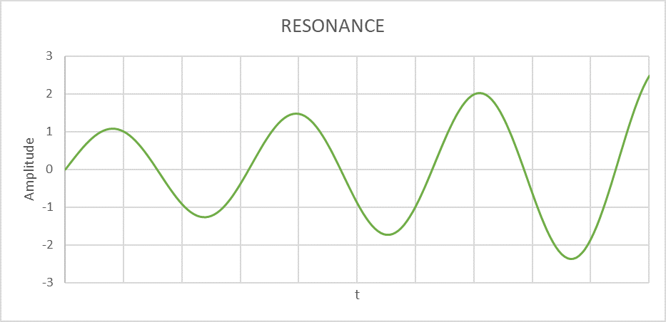
Fig. 3 – Time profile of resonant oscillation
Resonance is a desirable phenomenon in some industries, such as music, watchmaking, laser equipment, etc., but in engineering and automation, it is totally undesirable. Applications that are mainly based on precision and repeatability of motion would be unusable if resonance were to occur. Therefore, the resonance characteristics of the application, as well as the actuators (drives) used, must be taken into account when designing the individual components and the final assembly. For this reason, so-called modal analyses have to be carried out. These allow us to detect, at an early stage of the design process, the possible risks associated with the resonance of individual components or even of the entire system.
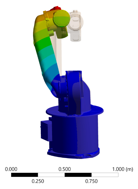
Fig. 4 – Example of natural frequency analysis
As an example, we can take the design of an industrial robot. The results of the modal analysis showed that the first modal, or natural frequency, is at 59Hz. This implies that the actuator speed should not reach 3540 rpm. The conclusion for the manufacturer of this robot is to either change the design or limit the output speed of the actuator if they want to avoid resonance and thus avoid the risk of permanent damage, even destruction of the robot.
In today’s era full of sophisticated IT analytical tools, it is therefore highly recommended to use their potential already during development and thus avoid complications in the later phase of production and operation of such devices.
This rule is also followed by the Slovak company SPINEA®, which uses these systems when designing its own products. It also offers this option to its customers and partners during the early stages of device development. The analyses concern both the individual components and the resulting whole. They contribute significantly to the improvement of the final product, the operational characteristics, and the overall durability of the customer’s equipment by their high evaluative value.
This is an article from the Spinea Blog
As a SPINEA sales partner our applications engineers are fully trained to specify and support SPINEA gearheads. Please call if you have an application you think may be suitable for a SPINEA high precision gearhead.
For details of the full Spinea range or for technical help contact us.